FastRobots-2025
ECE4160/5160-MAE 4190/5190: Fast Robots course, offered at Cornell University in Spring 2025
This project is maintained by FastRobotsCornell
CH340 USB to Serial Communication
Introduction
For most users, the CH340 driver software is embedded in their USB Serial drivers in their OS. For those that fail to communicate with the Artemis, even after following the debug steps in Lab 1A, you may need to install dedicated USB drivers from WCH and configure the SVL bootloader to enable proper communication between the computer and the Artemis board over USB.
Install CH340 Drivers
WCH makes drivers for each of their ICs and various operating systems.
- Linux/ FreeBSD: CH341SER_LINUX.ZIP
- Windows: CH341SER.EXE
- macOS: CH341SER_MAC.ZIP (Follow the dmg install instructions in the PDF).
Vist the WCH downloads page to check for the most up-to-date drivers.
Verify installation
First verify that the driver is working after successful installation.
Windows users
- Connect the Artemis board to the computer over USB.
- Go to Device Manager, look for USB-SERIAL CH340 in available ports (COM number may vary).
- Open the Arduino IDE, ensure correct board and port definitions and upload the Blink example.
Linux users
- Connect and disconnect the Artemis board to and from the computer over USB.
- Run the following command:
dmesg
- Check for this expected output:
[  xxx] ch341-uart ttyUSB0: ch341-uart converter now disconnected from ttyUSB0
[  xxx] ch341 3-2:1.0: device disconnected
- Connect the Artemis board to the computer over USB, ensure correct board and port definitions and upload the Blink example.
Mac users
- Connect the Artemis board to the computer over USB
- Open terminal and run the following command:
ls /dev/cu.wch*
There should be a USB serial port with address formatting cu.wchusbserial with some sequence of numbers after.
- Open the Arduino IDE, ensure correct board and port definitions and attempt to upload the Blink example.
If you cannot upload the Blink example, change the Baud rates and doublecheck your install.
- Next, modify the timing of the Blink example (e.g., change the ON time to 2 seconds instead of 1) and reupload the code (do not unplug the board). If you can successfully upload code, the driver install was the only fix needed. If not, we need to update the SVL bootloader software.
Update SVL bootloader software
The Artemis boards are equipped with two bootloaders. The Sparkfun Variable Loader (SVL) and the Ambiq Secure Bootloader (ASB). For the purposes of this class, we only need to use the SVL bootloader. Note: If you use the ASB, you may accidentally rewrite the registers for the SVL on the Apollo3 chip, you will need to reburn the SVL bootloader on the chip for future use of SVL.
When we added the apollo3 board package to the Arduino IDE, the library contents were saved in Arduino’s Library folder. Deep in these folders is the svl.py source code and the svl executable that runs when we call the SVL bootloader in the Arduino IDE.
- Go to Ardunio, open Settings/Preferences, and turn on verbose output during Upload.
- Upload code to the Artemis (does not matter if it succeeds or fails).
- The output text should list the filepath to the bootloader executable (generally the third line of the output).
- If you have a replacement executable file, delete the old version and save the new version here. Skip to step 9.
- The source code can be found in a directory two levels up. There should be an
svl.pyfile and a corresponding0x10000.ldfile. - You can open and modify the
svl.pyfile as needed with any python program. - Create an executable of the updated
svl.pycode with PyInstaller:
pyinstaller --onefile svl.py
- Make sure the new executable is moved to the directory from 3.
- Quit and reopen Arduino and burn any example file to the Artemis.
Note: if the Arduino output gives Permission Denied error, go to your CLI and type:
chmod +x your_filepath
Note: if the Arduino output gives a serial error, go to your CLI and type:
pip install pyserial
pip3 install pyserial
In Spring 2025, we performed these steps for you! This new executable has a hard-coded RTS signal to initiate bootloads (we found an error on Mac OS Sequoia machines that prevented repeated code uploads without power cycling the Artemis). Open this directory and replace the executable file with the one here (if you have an mac with an ARM CPU, otherwise, follow the instructions above). If this does not solve your problem, contact the teaching staff on Ed and we can help debug svl.py modifications.
Spring 2025 Error, Debug Process, and Solution
This error was particularly seen in ARM-based macs with macOS 14+. After downloading the WCH MAC dmg and completing install, the new wchusbserial port was consistently seen by the Arduino IDE and the device manager, but code could not be reuploaded to the board without a hard power reset (plugging and unplugging the board from the computer). Uploads could be seen on the RX LED on the Artemis board, confirming that information was being sent over USB, but the Apollo3 never entered bootloader mode.
Artemis Hardware
CH340E
The Artemis Nano uses a CH340E USB to Serial IC to convert USB serial communication to the standard RX/TX signals for the Apollo3 MCU:
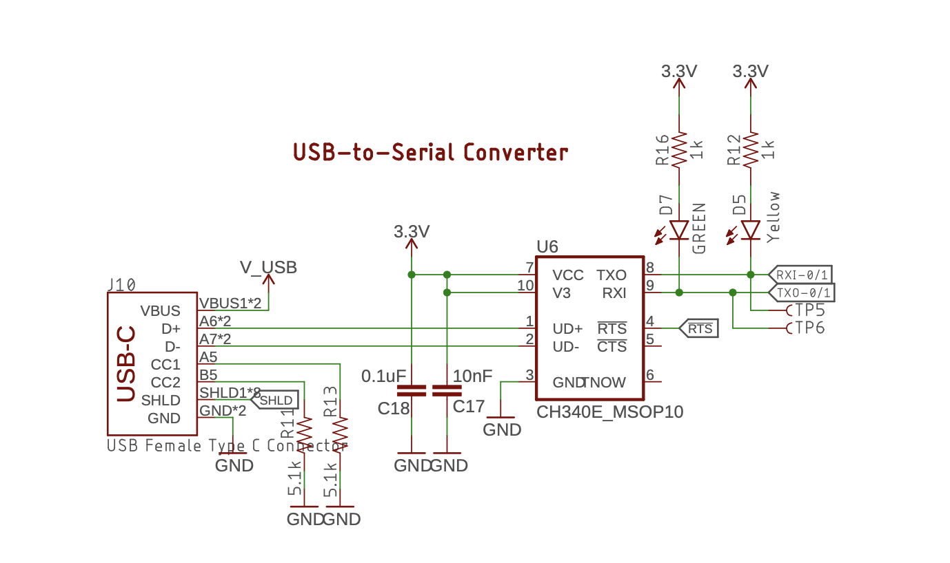
- VCC, V3, and GND: power pins
- UD+ and UD-: USB data signals
- TXO: Serial data output (from the IC)
- RXI: Serial data input (to the IC)
- iRTS: Modem request to send (output)
- iCTS: Modem clear to send (input – unused on the Artemis Nano)
- TNOW: Serial status flag (output – unused on the Artemis Nano)
Bootloader Reset Circuitry
The Artemis uses the iRTS signal to initiate a bootload. Many USB Serial drivers automatically send an RTS signal just before sending data, and the Artemis leverages this signal to create a very simple RC circuit to toggle the BOOT pin on the Apollo3 HIGH for a fraction of a second.
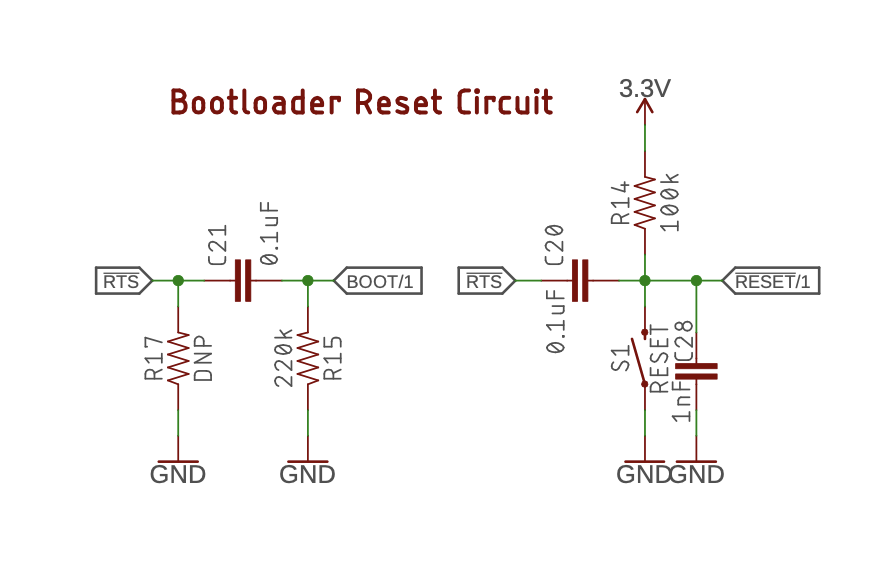
The Apollo3 then waits for an initialization signal from the bootloader to start uploading new code. If the Apollo3 does not receive this initialization signal within 50ms of this RTS signal, then the Apollo3 will start running previously uploaded code (from Artemis documentation).
Perceived errors
When the Artemis is first plugged in to the computer and we upload code through the IDE, we can successfully burn code. Errors in reuploading code happen if:
- The board has not had a hard power restart
- The serial monitor is left open (this causes intermittent code burning even if the board is freshly plugged in).
- The serial monitor is closed but the existing software has multiple Serial.print statements (this causes intermittent code burning even if the board is freshly plugged in).
Debugging strategy
Based on the perceived errors, I had already narrowed it down to the CH340E chip and the bootloader reset circuitry. Because this error was persistent across multiple boards, but working on many others, I knew that there wasn’t a specific hardware issue. I wanted to monitor the signals (iRTS, BOOT, and iRESET) on the Artemis board to determine their states during a successful code upload and an unsuccessful code upload. I added three wires to the back of the board that terminated in a 3-pin header.

I used an oscilloscope to measure the signals in real time during code upload.
Successful code upload
When the code first starts uploading, we can see a very short pulse on the RTS line (channel 1, yellow). The RTS signal is ACTIVE LOW, so it will remain high when unactivated. We see a corresponding signal on BOOT which is an ACTIVE HIGH signal (channel 2, blue).
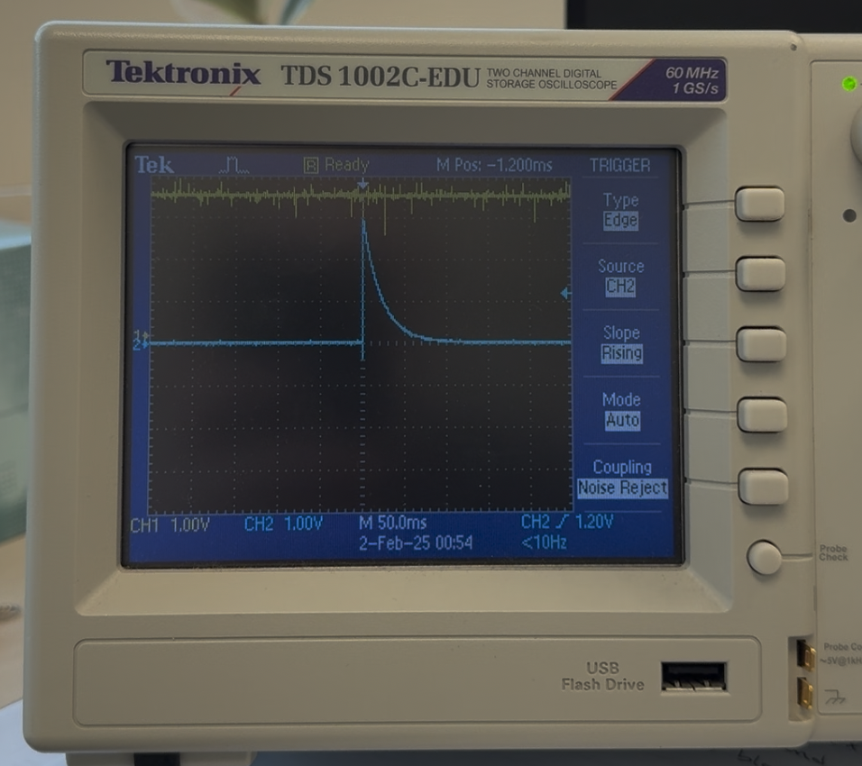
This same process happens for every single code upload.
Using a working machine that can repeatedly upload code, I made sure that there were no differences in the signal timing between inital code upload and subsequent code uploads with no power reset.
Unsuccessful code upload
The RTS line never initiates a pulse during code upload. The oscilloscope signals remain constant.
Check permissions for the USB Serial drivers
Using terminal, I wanted to check the USB settings on two mac machines (one working and one nonworking), so I used the following commands on the working and nonworking machines, respectively to list the install parameters and check for discrepancies:
stty -f /dev/cu.usb* -a
stty -f /dev/cu.wchusb* -a
There were none, and this is where my knowledge of USB drivers ends. After many unsuccessful prompts to chatgpt, and subsequent command line attempts to modify the permissions, I abandoned this route.
Rewire the Reset button to the iRTS line
Both the reset button and iRTS signal are ACTIVE LOW. By tying the Reset button to the iRTS line, I was hoping to trigger a BOOT signal during code upload attempts. Because the Arduino IDE takes some indefinite period of time to compile code and start uploading, I used Terminal to initiate the SVL bootloader:
python svl.py -f "my_filepath/Blink.ino.bin" -v /dev/cu.wch* -b 460800
As mentioned above, the svl.py code is provided with the Apollo3 library and the readme has excellent documentation on command line programming. You need to list the filepath to the bin file (in this case Blink), -v provides verbose output in the CLI, provide the port, and the baudrate with -b. This uploads the code much faster than through the Arduino IDE.
Shorting the wires between Reset and iRST, I was able to intermittently initiate the bootloader. By slowing down the baud rate, I could more repeatably get initialization, but this was still not 100% effective, and at higher baud rates, I could successfully use the button press every twenty attempts. We need to activate the BOOT pin no more than 50ms before the first initialization ping from the computer. Later than that, and the bootload fails. If you happen to start the bootload process but then hit the iRTS button again, the bootload fails (so repeatedly pressing the button at high frequencies was not a solution).
Send a serial command to change the value of the RTS line
We can open a serial connection with the Artemis board to change the value of the RTS line using python (make sure you have PySerial installed). Test that you can control the value of the RTS signal and confirm the change on the oscilloscope.
import time

ser = serial.Serial(port ="/dev/cu.wchusbserial110", baudrate=460800)

while True:
   ser.rts=True
   time.sleep(1)
   ser.rts=False
   time.sleep(1)
After I confirmed that I could control the RTS signal, I wrote an even shorter python script to initiate a short pulse on the RTS line (removed the delays) and then called the svl.py script to initiate the bootloader. However, because it took more than 50ms between calls, the Apollo3 failed to initialize.
Possible solutions
With this knowledge, I determined four possible solutions:
- Update the driver extension software to modify RTS signal permissions and execution.
- Contact WCH to ask about the driver extension software and request an update.
- Modify the bootloader code on the Artemis to enable longer delays between the BOOT signal and the initialization signal from the bootloader. This will enable us to reuse the RESET button to start the BOOT process during upload attempts.
- Modify the boodloader source code to send an RTS signal just before the initialization.
There could be other solutions, these were the four that I could think of! Curious to know if there are other, easier solutions. I am not a software engineer and so am always interested to learn new debug perspectives!
I chose the fourth option, as I am not a software engineer and eliminated the first option, I am impatient so eliminated the second option, and I am worried about direct writing dedicated bootloader registers and potentially breaking the ability to bootload future code so eliminated the third option.
Update svl.py
I know that I can command the iRTS signal HIGH and LOW using serial commands. So I needed to find where in the python script the bootloader initializes serial communication. An image of the main function is below, feel free to check it out if curious.
main function
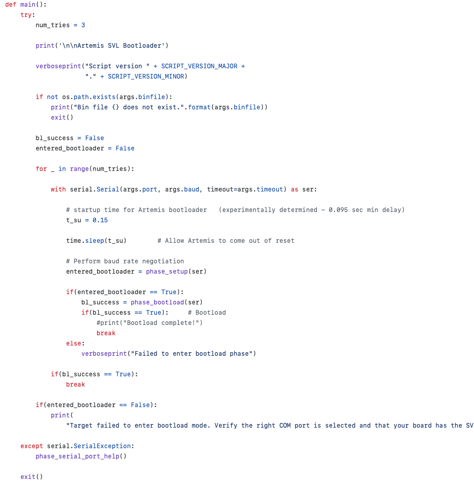
In the main function, there is a serial call after it checks for the presence of a binfile. It loops through the serial command a preset number of tries before stating that the MCU failed to bootload. To ensure that I was modifying the correct code, I changed num_tries = 5. This will give me five failed attempts instead of the standard three.
I reran the script and got five “Failed to enter bootload phase” responses, so I knew that I was modifying the code. I then added a parameter to the Serial command to set rtscts = True to redefine rtscts handshaking outside of the USB driver software.
with serial.Serial(args.port, args.baud, timeout=args.timeout, rtscts=True) as ser:
I reran the script and again got five “Failed to enter bootload phase” responses.
Next, I just added a short pulse immediately after serial communications initialized:
with serial.Serial(args.port, args.baud, timeout=args.timeout) as ser:
   ser.rts = False
   ser.rts = True
I reran the script and successfully uploaded the code! I changed the bin file and baud rate to ensure that this worked for different configurations, and had consistent results.
Create an executable file
To enable uploading through the Arduino IDE, I needed to create an executable file and store it in the Arduino filepath. Using pyInstaller, creating the executable is one line of code:
pyinstaller --onefile svl.py
I removed the old version and saved this new version in the filepath, reopened Arduino IDE and could successfully (and repeatably) upload code!